Wednesday, October 17, 2007

Next step?

Besides completing my Lightcuts implementation during the last week, I have searched for possible next steps in my thesis.
One possible extention to the Lighcuts algorithm, as already identified in the paper, is the addition of bounds on the visibility term. I have read a number of papers on this subject:
  • Shaft Culling For Efficient Ray-Cast Radiosity - Haines E. & Wallace J. (1991)
  • ShieldTester: Cell-to-Cell Visibility Test for Surface Occluders - Navazo I., Rossignac J., Jou J. & Shariff R. (2003)
  • Conservative Volumetric Visibility with Occluder Fusion - Schaufler G., Julie D., Decoret X. & Sillion F. (2000)
and found one other paper that might be interesting:
  • Ray Space Factorization for From-Region Visibility - Leyvand T., Sorkine O. & Cohen-Or D. (2003)
All these techniques have fairly large disadvantages in the context of the calculation of bounds on the visibility. For example the first paper can only guarantee total occlusion if it is cause by a single object (i.e. 1 triangle). In practice this will only work well if there are a number of large polygons in the scene. There do exist a number of extensions that can detect the aggregate occlusion of a number of objects by for example reconstruction larger planes from a number of smaller triangles. The second paper is only applicable to triangles and needs structural information about the meshes (ex. neighbors of a triangle). In the last paper, the scene is discretized which inevitably leads to missing small features (ex. small holes).
Further more all these techniques are quite expensive. This means they can only be used in very selective cases during lightcut calculation or only during a pre-processing phase.

The shaft-culling technique is able to efficiently detect clusters that are totally visible. This could be used to calculate lower bounds on the cluster contribution which results in better error estimates and lower cut sizes.

A totally different approach is to drop the deterministic nature of the lightcuts algorithm and use inexact estimates of the visibility. One possibility would be to first calculate a cut using the bounds and then construct a pdf over the resulting clusters using their estimated contribution. The total contribution of all lights can the be estimated by generating a number of samples from this pdf.
Ideally the user should be able to control the amount of determinism (i.e. the solution goes from the lightcuts solution to totally stochastic according to a parameter).
Saturday, October 13, 2007

Lightcuts implementation

During the past week I completed my lightcuts implementation. Concretely this means I added cosine weighted point lights and directional lights (clustering & bounds), a bound for the Blinn microfacet distribution and support for global illumination using the Instant Global Illumination algorithm as implemented in the igi plugin for pbrt.
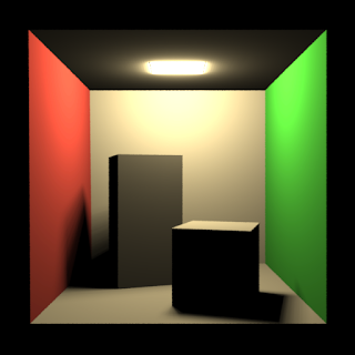
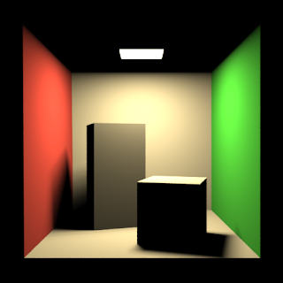
All of the following pictures where rendered using this updated implementation on my Core2 Duo T7100 system using 4 samples per pixel. The first picture is once again the cornell box but now using 1024 cosine weighted lights instead of omni directional lights with a maximum relative error of 2%. The total render time for this picture was 227s and the average cut size was 104.


The second picture shows a modified cornell box with glossy objects and global illumination. The total number of light sources used was 760000 which were mostly for the indirect light. The required time was 632s and the average cut size 206.


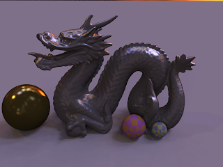
The final picture shows a glossy dragon statue lit by the grace environment map. This environment map was approximated by 256000 directional lights distributed evenly over the entire sphere of directions. The total render time was 1557s and the average cut size 218.

Saturday, October 6, 2007

Total illumination misinterpretation

After some more testing and re-reading the lightcuts paper I have come to the conclusion that the calculation of the total radiance estimate (used to determine what errors are allowed) in my implementation differs from the one used by the authors of the lightcuts paper. As described in my previous post, I used the maximum total illumination as an estimate of the total illumination. While the authors of the lightcuts papers do not state so explicitly they most likely used the current lightcut approximation as an estimate for the total illumination. This estimate is by definition always less then the maximum total illumination and will thus result in a lower allowed error per cluster.
Using the current lightcut approximation generally improves the estimate but is especially important in highly occluded regions because the difference with the maximum total illumination is largest here. I re-rendered the cornell box scene using this new total illumination estimate:
  • resolution: 512x512
  • samples/pixel: 4
  • pixel filter: gaussian
  • area light approx.: 1024 omnidirectional lights
  • render-machine: Core2 Duo T7100 (single core used) with 2GB ram
As you can see I used a different machine so the timings are not comparable to my previous test. The first picture shows the reference solution (795s). The following 2 pictures show the lightcuts approximation with a respective maximum relative error of 2% (182s) and 5% (107s). Both of the lightcuts pictures used a maximum cut size of 1024 (i.e. all lights) which is always used in the completely occluded regions due to the new total illumination estimate being 0. The average cut sizes where 119 and 73.


Like in my previous test, the final 2 pictures show the relative error. It is clear that the total illumination estimate used by the authors of the lightcuts paper is a lot better then using the maximum total illumination: the relative error is even in the highly occluded places very close to the target (avg: 0.36% and 0.95%; max: 2.1% and 3.5%).


Thursday, October 4, 2007

Lightcut error clarification

The error images in my previous post are the relative error of the lightcuts image w.r.t. the reference image (i.e. abs(lightcuts - reference) / reference). This error differs from the error bound used in the lightcuts algorithm because the reference solution is obviously not available during the lightcut calculations. The lightcuts algorithm uses an upper bound on the total illumination (further referred to as maximum total illumination or mti) to determine whether the maximum error for a particular cluster is acceptable (i.e. it is smaller then some percentage of the mti). So the lightcuts algorithm gives no real guarantee w.r.t. the real relative error. Such a guarantee would require using a minimum total illumination which is a lot harder then a maximum because a decent lower bound on the visibility term is necessary.
During cut refinement the estimate of the mti is also improved using the bounds computed for the refined clusters. This means that not only the error bounds on the individual clusters drops, but also the mti and thus the maximum allowed error.
In pseudo-code the lightcut algorithm is something like this:
rootUpperBound = calc. upper bound root cluster
mti = rootUpperBound
root.maxerr = rootUpperBound
cut = [root]
while(largest cluster error in cut > some% of mti) {
cluster = remove cluster from cut with largest error
left = cluster.leftchild
right = cluster.rightchild
leftUpperBound = calc. upper bound left cluster
rightUpperBound = calc. upper bound right cluster
if(left is leaf)
left.maxerr = 0;
else
left.maxerr = leftUpperBound
if(right is leaf)
right.maxerr = 0
else
right.maxerr = rightUpperBound
mti -= cluster.maxerr
mti += leftUpperBound + rightUpperBound
cut = [cut left right]
}
The lowering of the mti can result in some unexpected effects like a reduction in cut size for occluded pixels if the number of lights increases. This is caused by a cascade effect if too few light sources are used at these occluded pixels. At some point during cut refinement a leaf node is reached. Because the point is occluded, the mti will be significantly reduced (the previous node still had a non-zero upper bound). This results in more nodes that need to be refined which again results in new leaf nodes.
The use of the mti instead of the reference image in the calculation of the maximum acceptable error also explains the large relative errors in shadow boundaries as visible in the error images of my previous post. In the highly occluded regions the mti is significantly higher then the real illumination due to the poor visibility bound (i.e. everything is visible), so the lightcuts algorithm will allow too large errors.

Monday, October 1, 2007

First render

Last weekend I implemented a light tree construction algorithm for omnidirectional lights, bounds for omnidirectional lights and a trivial bound for the cos term (i.e. 1) and the diffuse brdf (this brdf is already a constant). Using this basic implementation I rendered some pictures of the famous cornell box. The setup for all pictures was as follows:
  • resolution: 512x512
  • samples/pixel: 4
  • pixel filter: gaussian
  • area light approx.: 256 omnidirectional lights arranged in a regular grid
  • render-machine: AMD X2 3800+ (single core used) with 1GB ram
The first picture shows a reference solution (i.e. sampling all lights) and rendered for for 234s. The next 2 pictures were rendered using the basic implementation with a maximum relative error of respectively 1% and 2%. These images rendered for 204s and 101s with a average cutsizes of 157 and 72 respectively.


The final 2 pictures show the relative error between the reference picture and the pictures rendered using the lightcuts algorithm. There are a few strangely colored pixel due to a division by zero in some (but not all) of the channels. Although the relative error on most pixels is far below the maximum relative error, some pixels (especially in dark regions) have considerably higher relative errors (up to 100% for the 1% relative error image and up to 300% for the 2% relative error image). It is not clear yet whether these are caused by a flaw in the implementation, some numerical issue or something else.